Distance learning reflection

Distance learning reflection

In week 7 of this semester, the Taoiseach ordered all educational institutions and schools for to close and to start implementing distance learning. I was worried at first as I did not know how well I was going to be able to work from home as I knew there was a lot of distractions. I was lucky as a lot of people were worried about the strength of the internet connection but mine was a good speed and I was able to access live lectures and discussions etc. I knew it was going to be challenging for me and all of us college students. To make it even more difficult, this happened mid-semester, so we had already begun projects like our sumo bot so continuing with this along with trying to complete group work was very challenging as we had no face to face contact. Tasks that would have been simple like meeting up to discuss sketches and designs were now very difficult.

I feel that this system of learning has been a good experience for me, and I found it enjoyable and beneficial, but I can see that this might not be the case for all students. This form of learning is very self-orientated and if you do not keep on top of work, it can become overwhelming. There is no lecturer or teaching assistant asking you every day of the week to submit the work, it is up to you if you submit that work or not. Distance learning can cause a massive drop in motivation for students. Jill M Galusha explains how ‘adult learning is not without problems, (however,) such as loss of motivation because of lack of face-to-face contact with teachers and peers. (Galusha, Jill M). This shows how students can not only loose motivation due to lack of face to face contact with teachers, but also peers. Peers can be a great support for students as they can bounce ideas off each other and help each other where necessary. Distance learning does not cut this out all together but does make it more complicated to do so.

Online lectures can be as useful as face to face lectures if not more helpful, if students engage. I found the online and recorded lectures useful because I engages and looked back on the lectures. A study from the American Association for Anatomy concluded that ‘Data indicated (that) 30% of the students did not use the LRS at all with 41% of the students using it very little (less than 10 times for a total of 131 recordings).’ (Thierry R.H Bacro). In this case LRS stands for lecture recording system. This shows just how little students on average will fully engage in the lecture recordings or live lectures simply because they feel that they do not have to.

Overall, I feel that the distance learning methods adopted by UL worked well for me, but I can understand how students will have difficulties in different areas.

References

Barriers to Learning in Distance Education, Galusha, Jill M, 1998.

Evaluation of a lecture recording system in a medical curriculum, Thierry R.H. Bacro, 2010.

Evaluation of prototype

Having completed the design stage and manufacturing stage we are happy with the end result. We did have to alter some of the working drawings as the dimensions were not to BS8888 standard. We also decided to alter the motor choice for our flipper arm. This was the biggest alteration we made to the robot design. After completing these changes we are happy with the final prototype. Although we did not have the opportunity to complete the manufacturing stage, we believe the basic design of our sumo bot would make it a strong contender when paired up to other sumo bots. One thing we would do differently if we were designing the sumo bot again, is to widen the rear wheels as I believe that the wheels would not have much grip on the surface of the ring. We also had a lot of spare weight left over (over half of the 1kg limit), so i feel that adding weight in this area would benefit the traction of the wheels. We would also be left with extra weight to position anywhere we need inside the sumo bot, which would have been decided through testing.

Below are some of the alterations we made to the sumo bot from our week 5 submission. Firstly we have the new motor setup, so we needed to design a new mounting system for the servo motor, which was a difficult shape and needed to be mounted at a right angle. I designed a L bracket with a slot cut out which utilized the mounting holes already present on the servo motor. We also had to alter the base section of the robot as the mounting holes in the base were also moved. Here you can see the new setup for the front flipper arm of the robot.

This was the original mounting bracket designed for the yellow DC motors.

This was the re-designed bracket for the servo motor.

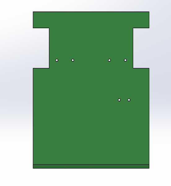
I also had to go back and change some of the working drawings of the original parts which were staying the same. Below is the newly dimensioned working drawing of the shell of the sumo bot. As you can see, it now conforms to the BS8888 standard.

Manufacturing 2

This week we would have been starting to manufacture the sumo bot. Due to the covid-19 outbreak we have decided to not go ahead with the manufacturing due to the lack of resources and lack or material. We will talk through the processes we would have been using and the materials we would have been using.

The base of the sumo bot.

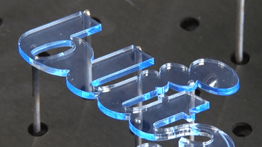
This base would have been made out of 3mm acrylic as can be seen in our working drawings.  We used 3mm acrylic for to ensure the robot has enough strength but also to keep weight down as the weight limit is 1kg. We had to decide on the most effective and accurate process for manufacturing this piece, so we decided to go with laser cutting. Due to the complex shape of the part, it would have been tricky to file down by hand and the positioning and small size of the holes meant it would have been difficult for to drill these with a pillar drill. Some of the holes were also close to the edges of the piece so drilling might have led to us cracking the piece. Due to these, laser cutting was clearly the most efficient process for us to use.

We sent the part file to the laser cutting software and that sent it to the cutter.

The process of laser cutting is described in depth in the previous manufacturing post. It is essentially a laser which is concentrated to a tiny area of the acrylic and cuts through the material with great accuracy and leaves a smooth finish. The pros for us when looking at laser cutting as a process option were:

1) Faster than filing and drilling

2) More accurate than filing and drilling

3) smoother surface finish than rough filing

We could not see any major draw backs when considering laser cutting so we decided to use it for the main shell and the base of the robot.

Flipper arm

Again, the flipper arm is going to be made from 3mm acrylic. We could have used sheet aluminium to reduce weight, but we knew that the arm must be strong and not flex when flipping opponents to be most effective. We carried out a test on 3 materials, 5mm Perspex, 3mm acylic and 2mm aluminium. We found the mass of each different material and then placed a 2kg weight on the object when it was suspended between two blocks. We observed the strength of each object and noticed that the aluminium began flexing. We noticed the 3mm acrylic held up to the 2kg weight (twice the weight that will be applied to it) and so did the 5mm Perspex. The Perspex was considerably heavier and so we decided to go with the acrylic to maximise strength and minimise weight.

To manufacture this piece, we looked again at laser cutting. But after seeing how long setting up the file and the machine to laser cut the body and base, we decided against laser cutting for the arm. We decided against it due to the part being a relatively simple shape with only 4 holes to be drilled in it. Although the holes were close to the edge, we decided to try file and drill the piece with a pillar drill first and set the drill to a slow speed to ensure it does not crack. The holes are small so we should be able to drill them using a pillar drill. We firstly marked out the piece on the acrylic ensure there is minimum waste. We cut out the shape of the piece with the band saw, leaving 2mm past each line for to file it down and ensure we can get a good finish on the acrylic. We used a rough file to get the material down to roughly 1mm from the line, and then used a smaller smoother file to get down further. We then used the draw filing technique and then used emery cloth for draw filing. This ensured a smooth finish. We then drilled the holes using the pillar drill on the slowest setting. This allowed us to drill the holes without cracking the piece. The holes were 3mm so we did not have to use a pilot hole. Once that was done, we then went back and put oil on the emery paper and got the final finish on the outer edges of the piece.

Evaluation of prototype

Overall we are pleased with how the prototype of our project has turned out so far and are happy with how all the components fit and will work inside of the bot, the overall design did not require any additional design features but some of our electronic components did we originally had planned on using a standard yellow cased motor to drive the cam for the flipper arm but have since come to realize through the feedback we received during the last submission that the motors would not be suitable as they would not be able to maintain the flipper and a constant height as them motors are not programmable in that way so we have changed that design to now incorporate a servo motor. After doing this we again looked the design of the bot shell ad came up with an extra defense mechanism that we though would work we would use a type of reverse hook mounted on the flipper arm itself to try hook other bots as they drove up out slanted front. This design idea would then stop that bot from reversing or sliding off the front of our bot

coding part 1

code1code11

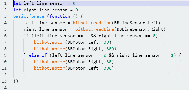
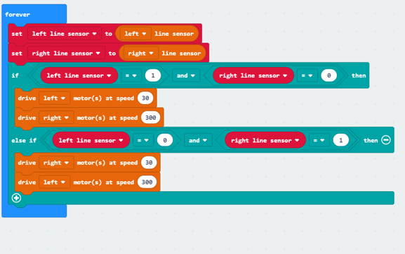
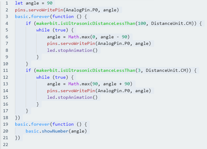
As can be seen above this is the coding we ae using to drive our bot within the ring the base of this code is that of a line follower robot as it has to stay within the white circle and not fall off the table that has a black ring around the edge, the code was changed so not it stops when it get the a darker colour instead of following the darker colour like a line follower.

This code was chosen as it was the most effective as we could easily change the speed at which each wheel would have turn depending on what side of the bot enters the darker region first. For example have it working slowly for testing and calibration of the electronic components and then speed it up for competition

code2code22

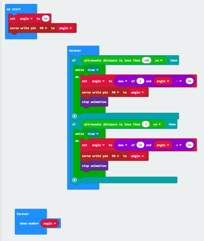
This is the code that we are going to be using for our flipper arm to lift other bots off the ground if they drive up on top of us. It uses a stepper motor fitted to a cam to raise and lower and flap, the servo motor will only have two positions set into it the highest setting to lift and stay up/lift up other bot and the resting position thus is where it will spend much of it time as the flipper will one be engaged as a defence mechanism

Manufacturing process


pres5pres6pres2

Base is a laser cut piece of acrylic

Laser cutting is a technology that uses a laser to slice materials. While typically used for industrial manufacturing applications, it is also starting to be used by schools, small businesses, and hobbyists. Laser cutting works by directing the output of a high-power laser most commonly through optics. The laser optics and CNC are used to direct the material or the laser beam generated. A commercial laser for cutting materials uses a motion control system to follow a CNC or G-code the same as a 3D printer of the pattern to be cut onto the material. The focused laser beam is directed at the material, which then either melts, burns, vaporizes away, or is blown away by a jet of gas, leaving an edge with a high-quality surface finish.

Advantages of laser cutting over mechanical cutting include easier work holding and reduced contamination of workpiece (since there is no cutting edge which can become contaminated by the material or contaminate the material). Precision may be better, since the laser beam does not wear during the process. There is also a reduced chance of warping the material that is being cut, as laser systems have a small heat-affected zone. Some materials are also very difficult or impossible to cut by more traditional means.

Step 1: Importing a CAD file and setting up parameters for the laser to follow.

Step 2: Open the hood of the laser and position the Perspex sheet in place.

Step 3: Start-up the Laser.

Step 4: Laser begins to engrave Perspex acrylic.

Step 5: Laser proceeds to cut the substrate.


The environmental impact from laser cutting plastics is primarily due to the fumes. The risk is dependent on the type of plastic. The fumes from certain types of plastics can be harmful to health, while others are harmless. Acrylic is by far the most laser cut material, then polyester, polycarbonate, and PVC in smaller quantities. acrylic, which is not harmful to the environment. However, fumes from laser cut acrylic has a distinctive smell that can cause discomfort, polycarbonate contains the substance “Bisphenol A” which is suspected of being an endocrine disruptor (Endocrine disruptors are chemicals that can interfere with endocrine (or hormonal) systems at certain doses. These disruptions can cause cancerous tumours, birth defects, and other developmental disorders. It is tempting to laser cut PVC. The result of laser cut PVC sheets are ok, but PVC releases hydrochloric acid when laser cut. The fumes will etches the machines and is harmful to the operators of the machines. Many coloured foils also contain PVC softeners – a fact that many are not aware of and therefore expose themselves to a small but constant concentration of hydrochloric acid.


Wheels are going to be made out on the lathe

A lathe is a machine tool that rotates a workpiece about an axis of rotation to perform various operations such as cutting, sanding, knurling, drilling, deformation, facing, and turning, with tools that are applied to the workpiece to create an object with symmetry about that axis, Most suitably equipped metalworking lathes can also be used to produce most solids of revolution, plane surfaces and screw threads or helices. The workpiece is usually held in place by either one or two centers, at least one of which can typically be moved horizontally to accommodate varying workpiece lengths. Other work-holding methods include clamping the work about the axis of rotation using a chuck or collet, or to a faceplate, using clamps or dog clutch.

Facing is the process of removing metal from the end of a workpiece to produce a flat surface When a lathe cutting tool removes metal it applies considerable tangential (i.e. lateral or sideways) force to the workpiece it should be flat, and perpendicular to the lathe axis. Facing is used to cut work to the desired length and to produce a surface from which accurate measurements may be taken.

Parallel Turning

This operation is adopted in order to cut the metal parallel to the axis. Parallel turning is done to decrease the diameter of the metal

The tailstock of a lathe can be used for drilling, with the aid of a drill chuck attachment
The usual starting point for drilling with a centre lathe is to use a countersink bit. This is used to drill slightly into the material and creates a starting point for other drills that are going to be used. Once a hole has been produced by a centre drill, machine twist drills can be used to enlarge the hole and if necessary, to drill all the way through. If a large diameter hole is needed, then a small hole is drilled first (e.g. 4mm dia). Then the hole is enlarged approximately 2mm at a time. Trying to drill a large diameter hole in one go will inevitably lead to the drill bit over heating and then jamming in the material. This is potentially dangerous.

Knurling is a process of impressing a diamond shaped or straight line pattern into the surface of a workpiece by using specially shaped hardened metal wheels to improve its appearance and to provide a better gripping surface.


Motor mounting bracket 3D printed

The 3D printing process builds a three-dimensional object from a computer-aided design (CAD) model, usually by successively adding material layer by layer, which is why it is also called additive manufacturing.[1] The term “3D printing” covers a variety of processes in which material is joined or solidified under computer control to create a three-dimensional object,[2] with material being added together (such as liquid molecules or powder grains being fused together), typically layer by layer. s of 2019, the precision, repeatability, and material range have increased to the point that some 3D-printing processes are considered viable as an industrial-production technology, whereby the term additive manufacturing can be used synonymously with “3D printing”. One of the key advantages of 3D printing is the ability to produce very complex shapes or geometries, and a prerequisite for producing any 3D printed part is a digital 3D model or a CAD file.

The most-commonly used 3D-printing process (46% as of 2018) is a material extrusion technique called fused deposition modeling (FDM).[4] While FDM technology was invented after the other two most popular technologies, stereolithography (SLA) and selective laser sintering (SLS), FDM is typically the most inexpensive of the three by a large margin, which lends to the popularity of the process.


Slicing is dividing a 3D model into hundreds or thousands of horizontal layers and is done with software. Some 3D printers have a built-in slicer and let you feed the raw .stl, .obj or even CAD file. When your file is sliced, it’s ready to be fed to your 3D printer. This can be done via USB, SD or internet. Your sliced 3D model is now ready to be 3D printed layer by layer.

G-code is a language that humans use to tell a machine how to do something. With 3D printing, g-code contains commands to move parts within the printer. G-code consists of G- and M-commands that have an assigned movement or action.

Example code:

code

11 →  Indicates the line of code and is used for reference

G/M →  Blue Text is a G- or M-command

Red Text defines certain parameters

F → Speed

X/Y/Z → Coordinates

E → Feeder movement

wheel 3d

week 5 feedback

Portfolio feedback

Today we handed up our portfolio as part of the first submission, we were overall very happy with the feedback that was given to us, as now know that there are a few areas that we need to change and work on further, some of the concerns that were raised with us were.

  • We will need to go back over and redo some of sketching and solidworks renders as they were not the clearest
  • Drawing sheets not up to BS8888 standards and Lack of colour
  • There was also some data missing that we now know should have been included these include the list of figures.

Overall, we are very happy with the project so far and with the feedback we have received

Analog pin testing

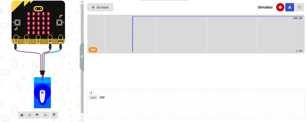
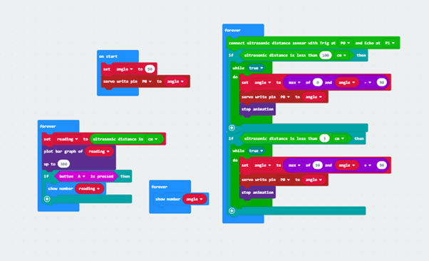
This week we conducted the analogue pin testing for both of our codes to ensure they are both operating correctly and constantly reading a range of values. We are using a line sensor and an ultrasonic sensor, so we want the Microbit to read and tell us the light values and the distance away from an object the sumo bot is. Because the line sensor gives us a digital reading and not an analogue (either on the line,1, or off the line, 0) we could not complete the analogue pin testing for this code, but we did run it to ensure it was working correctly. As you can see below, the code is operating correctly and are reading a range of values. They are also triggering the motors to complete a task in each case. When the ultrasonic sensor reads values that are lower than a predetermined value, it will activate the servo motor to move the flipper arm up at 90 degrees.

Week 5 – Feedback

This week we received feedback on our portfolio to date. Overall we were happy with this feedback but did receive some areas to improve on for the final submission.

Our solid works working drawings dimensions were not to Bs8888 standard in some areas. Some drawings were not dimensioned fully and some overall dimensions were situated on the inside of smaller dimensions which we will work on to rectify before the final submission.

We were also advised to render some of the concept sketches further as some had no colour etc.

We also had not list of fugues for our project so we will add one in for the final submission.

Overall we agreed fully with the feedback and now know what we need to complete and what we need to modify for the final submission.

Create your own website, free on WordPress.com.Create your own website.
Start free